

 Products
FT8261 series Two wire Wave Guided Radar Level System
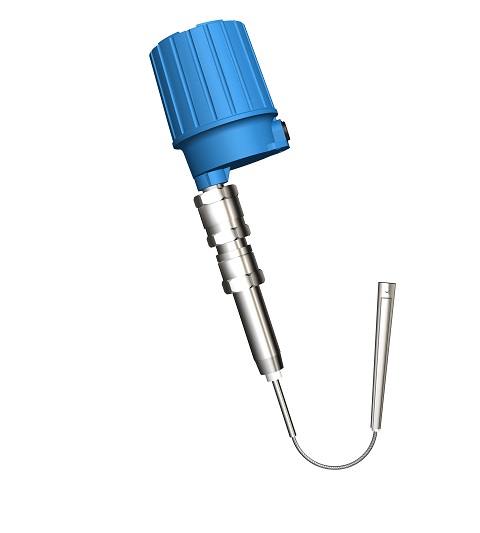
FT8261 serial is a general purposed two wire continuous guided pulse radar product, use for most industrial applications. Instrument is comprised for one electronic unit and a rod/cable sensing element, probe could choose multiple material, also could be installed integral or remote. This product is suitable for many continuous measurements.
》》》》Operation Principle
Radar, a technology that earliest is used for military purpose, measure the target distance or direction through the electromagnetic wave emission and return.
Guided pulse radar is a patented knowledge property right of our company. It is an one dimension guided pulse radar in pure radar system. The instrument emits a very low energy small pulse electromagnetic wave, the wave transmit along with a conductor at velocity of light, when come across a bigger resistance change(such as a liquid interface), then reflect amount of energy back, then use a super high-speed circuit and component record the time difference between the emission and reflection of the electromagnetic wave, that is the wave transmission distance, also the distance between the instrument and liquid interface(liquid level). The instrument use the most advanced software and hardware processing technology, it has a strong data processing ability, assure the reflection atlas could be reliable identified.
》》》》Character
Ø Super data processing ability assure reliable signal identification
Ø Regardless vessel shape change
Ø Ignore electricity, insulation, temperature, pressure, or density change
Ø Neglect dust, vapor or foam affection
Ø No moving part, avoid period maintenance
》》》》Typical Application
Ø Liquid、light slurry、granular、interface、powder
Ø Water、acid、sparse alkali、oil、food、raw coal、oil/water interface、coal powder、cement、 lime powder、flour
》》》》Specifications
Ø Measuring rate of facility: CAT II, transient over voltage 2500V, only use the equipment for measurements within measurement category I and II
Ø Output:two wire 4~20mA HART protocol
Ø Measuring Type:Level(DIR) or Distance(REV) software adjustable
Ø Power requirement:24VDC(15~35VDC)(for intrinsic safe 17~30VDC)
Ø Power: 1W
Ø Accuracy: 0.25% FS or 15mm(which greater)
Ø Resolution: 3mm(standard)
Ø Temp. Effect: 0.1% / 10℃(18℉)
Ø Load Resistance: output loop resistance 450Ω
Ø Ambient Temp.: -40~+70℃(-40~158℉)
Ø Process Temp. : T1:-40~+420℃;T2:-40~+270℃; T3:-40~+170℃ ;T4:-40~+105℃; T5:-40~+70℃;T6:-40~+60℃.
(Effect of the process temperature on the environment temperature should not exceed the
environment temperature requirements of the instrument.)
Ø Response Time: < 1 second
Ø Time Delay:1~90seconds adjustable(by software)
Ø Spark protection (for sensing element): anti-surge strike 1KV, anti-static 4KV/8KV
Ø Radio protection(Built-in filter):instrument pass through 10V/m space electromagnetic field and
3V/m electromagnetic field current injection tests
Ø Range: 0~5m(rod), 0~25m(cable)
Ø Electrical connection:M20×1.5 (3/4” NPT optional )
Ø Process connection:NPT Thread(standard, BSPT optional) , 4” Flange (GB standard, other optional)
Ø Housing Material: Die casting aluminum epoxy coating
Ø Ingress protection:IP67
Ø Explosion-proof rating:Ex ia IIC T1~T6 Ga; Exia IIB T1~T6Ga(insulating probe)
Ø Approval:PCEC/NEPSI, for other approval please consult factory
》》》》FT8261 Installation Requirements
l Installation、Utility & Maintenance of the instrument should comply with the instruction manual and
GB50257《Construction & Verification Standard of Electrical apparatus mounting in explosion or
flaming dangerous area》、GB3836.15 & GB3836.13 requirements.
l The mounting location of the instrument should free of vibration, high temperature, corrosive atmospheres, or any possibility of mechanical damage for maximum service life. If this is not possible, consider a remote system installation. Ambient temperature should be between -40 ~70oC (-40 ~158oF).
l Instruments installed outdoors in areas of lightning strikes should be installed with lightning protection.
l DO NOT ADOPT MONO-COMPOSITION ENCAPSULAION SEALING inside of instrument housing since most of that kind of encapsulation will contain acetic acid. (Acetic acid could decay the electrical component.) Please consider to use SPECIAL DOUBLE-COMPOSITION ENCAPSULATION (non-erosive).
l The instrument has ground terminal on its housing. Please connect the terminals to the field ground properly during installation. For non-metallic vessel/tank installation, the filed should provide a standard ground. CONNECT TO DYNAMIC GROUND IS FORBIDDEN!
l Cable inlet should meet GB4208 standard requirements reach IP65 code to ensure reliable electrical connections. It will avoid water or other corrosive gas destroys the electronic unit.
l Do not open sensing element or loosen sealed gland. That may cause system leakage.
l Do not install the sensing element directly under a flow stream or feed line. If this is the only position available, use a baffle or shield above the probe to keep it out of the flow stream.
l Only the mounting screw or flange part of the sensing element need be well connected to the vessel, reliable sealed and electrical connected properly. Any other parts of the sensing element should not touch the vessel for good insulation.
l Review the installation distance when mounting rigid probe. Keep the rigid probe at least 300mm away from the vessel wall. For cable probe, keep it as straight as possible and at least 500mm away from the vessel wall to avoid hitting the vessel wall (shorted to earth.).
l For agitation、gas/material flow fluctuation vessel, except avoid directly mechanical damage on sensing element, middle support (for rigid probe)/bottom anchor (for cable probe) of sensing element need be considered to avoid indirect mechanical broken under long-term utility. Please note: the support/anchor must be insulated with the sensing element. The insulating material should be high insulation, low hardness, lubricant and anti-abrasion material such as PTFE etc. Otherwise, periodical maintenance need be considered to avoid linkage loss.
l Keep the end of probe weight as far as possible to the cone part of the vessel under long range granular/powder application, since the pulling force of the material will increase tremendously at cone part. If necessary, the maximum length to go into cone should not bigger than 20% of the vessel O.D
l Under vertical installation, the rigid part of the cable probe should not less than 100mm.
l For intrinsic-safe instrument installation, the loop should come with approved barrier according to GB3836.1 & GB3836.4 explosion-proof standard requirements.
l 24VDC Instrument power noise should be lower than 100mV.
l Power wire should meet IEC60245/60227 standard requirements Recommended as 3 terminal armature cable, cable O.D. should less than 12mm, conductor material of the cable is copper, section area should between 0.13 –2.1 mm2(AWG14-26), insulating capability 1500V. And associated switch should meet IEC60947 requirements. Do not make the unshielded cable parallel with AC power supply cable for long distance..
l Strict follow “STOP OEPN THE LID WHILE POWER ON” during field operation or maintain, recommend
to operate 10 minutes after power off.
l Avoid risk of ignition from the impact or friction of Aluminum Alloy housing!