

 Products
FT836X series Ultrasonic Level System
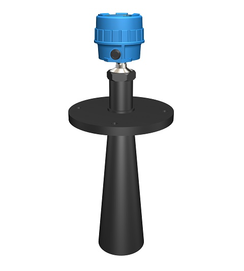
FT836Xserial two wire Ultrasonic level system could be used in most liquid applications. It consists of one
electronic unit、one enclosure and one sensing element. FT836X ultrasonic product is a non-contact instrument
suitable for many kinds of continuous level measurement.
Ultrasonic sensor translates the electrical pulse as sound energy and emit out, when the sound reach the material surface, it will be reflected back. Then the sensor collect the feedback energy transfer it as the electrical signal to analyze. The time interval from the sending to receiving of the ultrasonic pulse (transmit as sound rating) is directly proportion to the distance between the sensor to process material surface. So relationship of the distance(S)、sound rating(C)and the transmission time(T) could be indicated as: S=C×T/2.
Because all the ultrasonic pulse will has a definite width, so it will cause a supraposition between the emission and reflection in the closer area to the sensor, this distance can’t be identify and measure. Normally we call this area as Dead Zone. The dead zone range depends on sensor design.
The energy amplitude of emission from the sensing element will be decreased after it leaves the surface, the long the distance is the small the value is. Maximum sound energy go straightly along the transfer axial which is vertical to the S.E. surface. While the energy go down to half(-3dB), cone boundary line will focus on the transmission axis of a circle, known as the beam, the irradiation angle of the beam is called the beam angle.
》》》》Characters
Ø Advanced microprocessor and echo processing technology makes the instrument suitable for most filed applications
Ø “Multiple false echo memory” function help the instrument recognize the correct echo signal among multiple false echoes to have a right measurement result
Ø Built-in temperature sensor could do self-compensation for the output
Ø Chinese/English option in menu, LCD display makes calibration more convenient
Ø Various display option such as distance, level, current, percentage etc directly give customer their required output signal
》》》》Typical Application
Ø Liquid
Ø Slurry
》》》》Specifiactions
Ø Measuring rate of facility: CAT I, transient over voltage 1500V, only use the equipment for measurements within measurement category I
Ø Output:4~20mA
Ø Measuring Type:Level(DIR) or Distance(REV) software adjustable
Ø Power requirement: 15~30VDC
Ø Dissipation power: <1W
Ø Accuracy:10mm or 0.5%FS (which greater)
Ø Resolution:4mm
Ø Temp. effect:0.2% / 10℃(18℉)
Ø Load resistance:24VDC output loop resistance 450Ω
Ø Ambient Temp.:T5:-40~+70℃(-40~158℉);T6:-40~+60℃(-40~140℉)
(Effect of the process temperature on the environment temperature should not exceed the
environment temperature requirements of the instrument.)
Ø Response time: < 2 S
Ø Time Delay:1~90seconds (adjustable)
Ø Measuring Span:Max.5m、10m、20m(use different sensor for difference range)
Ø Beam angle:Min. 12°
Ø Electrical connection:M20×1.5 (3/4” NPT optional)
Ø Process connection:G 2A screw mounting or DN150 flange mounting (other optional)
Ø Housing Material: Die casting aluminum epoxy coating
Ø Ingress protection:IP67
Ø Explosion-proof rating:Exd IIC T5/T6 Gb
Ø Approval:PCEC/NEPSI, for other approval please consult factory
》》》》FT836X Installation Requirements
l Installation、Utility & Maintenance of the instrument should comply with the instruction manual and
GB50257《Construction & Verification Standard of Electrical apparatus mounting in explosion or flaming dangerous area》、GB3836.15 & GB3836.13 requirements.
l The mounting location of the instrument should free of vibration, high temperature, corrosive atmospheres,
or any possibility of mechanical damage for maximum service life. If this is not possible, consider a remote system installation. Ambient temperature should be between -40 ~70oC (-40 ~158oF ).
l Instruments installed outdoors in areas of lightning strikes should be installed with lightning protection.
l DO NOT ADOPT MONO-COMPOSITION ENCAPSULAION SEALING inside of instrument housing since most of that kind of encapsulation will contain acetic acid. (Acetic acid could decay the electrical component.) Please consider to use SPECIAL DOUBLE-COMPOSITION ENCAPSULATION (non-erosive).
l The instrument has ground terminal on its housing. Please connect the terminals to the field ground properly during installation. Keep ground wire resistance less than 0.5Ωand the length as short as possible.
l For non-metallic vessel/tank installation, the filed should provide a standard ground. CONNECT TO DYNAMIC GROUND IS FORBIDDEN!
l Cable inlet should meet GB4208 standard requirements reach IP65 code to ensure reliable electrical connections. It will avoid water or other corrosive gas destroys the electronic unit.
l Do not open sensing element or loosen sealed gland. That may cause system leakage.
l Do not install the sensing element directly under a flow stream or feed line. If this is the only position available, use a baffle or shield above the probe to keep it out of the flow stream.
l Only the mounting screw or flange part of the sensing element need be well connected to the vessel, reliable sealed and electrical connected properly. Any other parts of the sensing element should not touch the vessel for good insulation
l Keep the sensing element at least 500mm away from the vessel wall.
l For agitation、gas/material flow fluctuation vessel, please consider a isolated buffer for good measurement.
l Keep sensing element datum at least 100mm into the vessel, if can’t, please refer to following typical mounting drawing.
l For other consideration, please refer to following typical mounting details.
l For explosion-proof instrument installation, cable inlet should come with approved cable accessory such as XP fittings or XP steel conduit sealing according to GB3836.1 & GB3836.2 explosion-proof standard requirements.
l 24VDC Instrument power noise should be lower than 100mV.
l Power wire should meet IEC60245/60227 standard requirements Recommended as 3 terminal armature cable, cable O.D. should less than 12mm, conductor material of the cable is copper, section area should between 0.13 –2.1 mm2(AWG14-26), insulating capability 1500V. And associated switch should meet IEC60947 requirements. Do not make the unshielded cable parallel with power supply cable for long distance..
l Strict follow “STOP OEPN THE LID WHILE POWER ON” during field operation or maintain, recommend
to operate 10 minutes after power off.