

 Products
FT8021 series RF admittance level switch
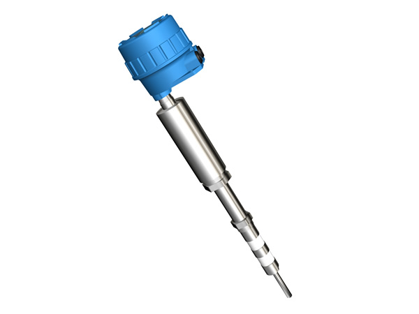
FT8021 serial Two Wire Smart RF admittance level switch 》》》》
FT8021 Series two wire smart RF admittance level switch, used for most position limitation control requirements such as raw material/product handling or storage of civil/industrial applications. It could be used to measure granular、powder、 slurry 、liquid or interface of two different liquids.
The product adopts an unique technology base on our intelligence hardware design, guarantees the effective process level identify and judgment.
Its power is standard two wire 24V DC power supply, output is current. 8mA refer to no process material found, 20mA refer to touch process material.
》》》》Operation Principle
As stems from capacitance level control technology, the Radio frequency admittance technology is a more advanced level control technology with a better coating rejection ability (material adhere on the sensing element is called as coating)、more reliable operation、higher accuracy、wider application. “Admittance” in “Radio frequency admittance” means the reciprocal value of the impedance in electricity, it includes resistance、capacitance and inductance. While “Radio frequency” means high frequency, so the radio frequency admittance could be understand as a method to measure admittance through high frequency current.
The main difference between capacitance technology and Point Driven Shield Radio Frequency level technology is due to the Point Driven Shield RF technology adopts a three terminal driven shield circuit and adds other measuring variables as ”impedance”, this not only resolve the temperature drift in the connecting cable but also resolve the sensing element coating problem.
》》》》Character
Ø Free calibration: No field calibration needed
Ø Universal power supply: 24VDC two wire
Ø Remote Communication: HART协议
Ø Intrinsic safe
Ø Free Maintenance: No period maintain or replacement needed as other paddle、vibration or
Ø mechanical switches, the parts will not occur block、broken or abrasion
Ø Coating rejection:Three terminal Driven-shield electronic design makes the instrument ignore the
Ø coating affection on the vessel wall or sensing element, no period clean or re-calibration needed
Ø Wide application:process temperature could run from -183℃~815℃, process pressure could be
vacuum~100bar
Ø Two color LED indication:red-alarm, green-normal, real-time indication
Ø Quick electrical connection:double electrical connections make the wiring more safe and
convenient
Ø Better drive ability:center rod to shield 500Ω, shield to ground 150Ω
Ø Spark protection:Built-in 1000V spark protection、surge and 4kV/8kV static limitation to assure
electronic unit work properly and away damage
Ø Electronic unit:Hockey pock design makes unit easy for mounting, reliable for field service
Ø Easy installation:instrument could be mounted in the field through the vessel screw or flange,
could be selected as integral or remote configuration, easy for installation and calibration
》》》》Typical Application
Ø Liquid:conductive and insulating liquid(include liquefied gas)
Ø Slurry:conductive and insulating slurry
Ø Granular:food、plastic chips、coal etc
Ø Interface:liquid interface between two different dielectric constants
Ø Powder:plastic powder、cement or fly ash etc.
》》》》Specifications
Ø Measuring rate of facility: CAT I, transient over voltage 1500V, only use the equipment for measurements within measurement category I
Ø Output:software adjustable, default setting is High alarm i.e. 20mA±0.2mA is alarm(red LED);8mA ±0.2mA is normal(green LED), HART protocol ; LED indication
Ø Power requirement:12-35VDC communication requires: 15~35VDC
Ø Dissipation power: less than 0.5W
Ø Resolution:0.2pFor lower
Ø Set point Accuracy: <1mm(0.04”)or 0.5pF (conductive); <20mm(0.79”)or 0.5pF (insulating)
Ø Temp. Effect:0.25% / 10℃(18℉)
Ø Load resistance:24VDC output loop resistance 600Ω
Ø Fail safe:High (HLFS) or low (LLFS) field adjustable
Ø LED Indications:Red- level alarm ;Green-system normal
Ø Calibration: Free calibration for most conditions
Ø Ambient Temp.:T5:-40~+70℃(-40~158℉);T6:-40~+60℃(-40~140℉)
(Effect of the process temperature on the environment temperature should not exceed the
environment temperature requirements of the instrument.)
Ø Response time:<1 second
Ø Time delay:1~90seconds(software adjust)
Ø Spark protection (for sensing element):anti-surge strike 1KV, anti-static 4KV/8KV
Ø Radio protection(Built-in filter):instrument pass through 10V/m space electromagnetic field and
3V/m electromagnetic field current injection tests
Ø Sensing element IL:0.5m(19.7″)(standard),0.1m(3.9″)~20m(787.4″)(optional)
Ø Cable length:5m(197″)(standard),0.1(3.9″)~50m(1968.5″)(optional),
>50m(1968.5″)~ 100m(3937″)(consult factory)
Ø Electrical connection:double M20×1.5 (3/4” NPT optional )
Ø Process connection:NPT Thread(standard, BSPT optional) , Flanges (optional)
Ø Housing Material: Die casting aluminum epoxy coating
Ø Ingress protection:IP67
Ø Explosion-proof rating:Exia IIC T5/T6 Ga
Ø Approval:PCEC/NEPSI, for other approval please consult factory
》》》》Probe(sensing elem
|
Probe No. |
Probe Insertion Length(IL) |
DSH |
Wetted Material |
Insulation |
S.E. Mounting |
S.E. Type |
Weight/ anchor |
Temperature/Pressure |
Applications |
|
78 |
S.t.500mm(19.7")/250mm(9.8”) Max. 2m(78.7") |
250mm(9.8")/80mm(3.1”) 450mm(18”)/650mm(26”) |
304SS(s.t.) Other optional |
PPS |
3/4"BSPT |
O.D. 9mm(0.35") |
NO |
230℃/1.0MPa (446℉/145psi) 120℃/1.6MPa (248℉/232psi) |
Mid-Temperature Low pressure |
|
79 |
S.t.500mm(19.7")/250mm(9.8”) Max. 2m(78.7") |
250mm(9.8")/80mm(3.1”) 450mm(18”)/650mm(26”) |
316SS(s.t.) |
PEEK |
3/4"BSPT |
O.D. 9mm(0.35") |
NO |
230℃/1.0MPa (446℉/145psi) 120℃/1.6MPa (248℉/232psi) |
Mid-Temperature Mid-pressure |
|
80 |
S.t.500mm(19.7") Max.2m(78.7") |
250mm(9.8") Other optional |
304SS( s.t.) |
PTFE |
1 1/2"BSPT |
O.D.22mm(0.87") |
NO |
230℃/常压(446℉/0 psi) 100℃/1.6MPa (212℉/232psi) |
Heavy duty Anti-agitation |
|
81 |
Flat 205mm(8”)×205mm(8”) |
304SS( s.t.) |
UR |
170mm(6.7”) ×170mm(6.7”) |
Three terminal flush mounting |
NO |
80℃/0.01MPa (176℉/1.5psi) |
Heavy duty Anti-mechanical shock |
|
|
82 |
S.t.500mm(19.7") Max.5m(197") Rod |
250mm(9.8") Other optional |
304SS( s.t.) |
Ceramic |
1 1/4"BSPT |
O.D. 9mm(0.35") Three terminal |
NO |
815℃/0.1MPa (1500℉/15psi) 300℃/2.5MPa (572℉/363psi) |
High temperature |
|
82A |
S.t.500mm(19.7") Max. 25m(984") Cable |
250mm(9.8") Other optional |
304SS( s.t.) |
Ceramic |
1 1/4"BSPT |
O.D. 4mm(0.16”) Three terminal |
NO |
815℃/0.1MPa (1500℉/15psi) 300℃/2.5MPa (572℉/363psi) |
High temperature Long range |
|
82B |
S.t.500mm(19.7") Max. 5m(197") Rod |
250mm(9.8") |
304SS( s.t.) |
Ceramic |
1 1/4"BSPT |
O.D. 9mm(0.35") Three terminal |
NO |
815℃/0.1MPa (1500℉/15psi) 300℃/16MPa (572℉/2320psi) |
High-temperature High-pressure |
|
82C |
S.t.500mm(19.7") Max.5m(197") Rod |
250mm(9.8") Other optional |
316L( s.t.) |
Ceramic |
1 1/4"BSPT |
O.D. 9mm(0.35") Three terminal |
NO |
815℃/0.1MPa (1500℉/15psi) 300℃/10MPa (572℉/1450psi) |
High-temperature Corrosion |
|
83 |
S.t.500mm(19.7") Max. 8m(315") |
250mm(9.8") Other optional |
304SS( s.t.) |
PPS |
3/4"BSPT |
O.D. 9mm(0.35") Three terminal cable |
YES |
230℃/1.0MPa (446℉/145psi) 120℃/1.6MPa (248℉/232psi) |
Mid-Temperature Low pressure |
|
92 |
S.t. 500mm(19.7") Max. 2m(78.7") |
250mm(9.8") Other optional |
304SS( s.t.) |
PTFE |
3/4"BSPT |
O.D. 9mm(0.35") Three terminal rod |
NO |
230℃/4.0MPa (446℉/580 psi) 40℃/6.3MPa (104℉/913psi) |
Mid-Temperature Mid-pressure |
|
93 |
Max. 3m(118") |
304SS( s.t.) |
PTFE |
1 1/2"Tri-clamp Other optional |
O.D. 12mm(0.47") Two terminal rod |
NO |
230℃/2.5MPa (446℉/363psi) 40℃/6.3MPa(104℉/913psi) |
Sanitary 3A probe |
|
|
94 |
Max. 3m(118") |
250mm(9.8")/80mm(3.1”) Other optional |
304SS( s.t.) |
PTFE |
3/4"BSPT |
O.D. 18mm(0.71") Three terminal rod |
NO |
230℃/4.0MPa (446℉/580psi) 40℃/6.3MPa(104℉/913psi) |
Corrosive liquid |
NOTE: 1. DSH(shield length)must go into the vessel wall over 50mm. 2. For following application, cooling extension is recommended: 1) FS82 under and above 400℃ applications. 2)FS92、FS94under and above 180℃/4.0MPa applications.
》》》》FT8021 Installation Requirements
l Installation、Utility & Maintenance of the instrument should comply with the instruction manual and
GB50257《Construction & Verification Standard of Electrical apparatus mounting in explosion or flaming dangerous area》、GB3836.15 & GB3836.13 requirements.
l The mounting location of the instrument should free of vibration, high temperature, corrosive atmospheres,
or any possibility of mechanical damage for maximum service life. If this is not possible, consider a remote system installation. Ambient temperature should be between -40 ~70oC (-40 ~158oF ).
l Instruments installed outdoors in areas of lightning strikes should be installed with lightning protection.
l DO NOT ADOPT MONO-COMPOSITION ENCAPSULAION SEALING inside of instrument housing since most of that kind of encapsulation will contain acetic acid. (Acetic acid could decay the electrical component.) Please consider to use SPECIAL DOUBLE-COMPOSITION ENCAPSULATION (non-erosive).
l The instrument has ground terminal on its housing. Please connect the terminals to the field ground properly during installation. For non-metallic vessel/tank installation, the filed should provide a standard ground. CONNECT TO DYNAMIC GROUND IS FORBIDDEN!
l Cable inlet should meet GB4208 standard requirements reach IP65 code to ensure reliable electrical connections. It will avoid water or other corrosive gas destroys the electronic unit.
l Do not open sensing element or loosen sealed gland. That may cause system leakage.
l Do not install the sensing element directly under a flow stream or feed line. If this is the only position available, use a baffle or shield above the probe to keep it out of the flow stream.
l Only the mounting screw or flange part of the sensing element need be well connected to the vessel, reliable sealed and electrical connected properly. Any other parts of the sensing element should not touch the vessel for good insulation.
l For horizontal mounting, sensing element should be pointed downward to the vessel, angle around 10~20o.
l Review the installation distance when mounting rigid probe. Keep the rigid probe at least 100mm away from the vessel wall. For cable probe, keep it as straight as possible and at least 300mm away from the vessel wall to avoid hitting the vessel wall (shorted to earth.).
l For agitation、gas/material flow fluctuation vessel, except avoid directly mechanical damage on sensing element, middle support (for rigid probe)/bottom anchor (for cable probe) of sensing element need be considered to avoid indirect mechanical broken under long-term utility. Please note: the support/anchor must be insulated with the sensing element. The insulating material should be high insulation, low hardness, lubricant and anti-abrasion material such as PTFE etc. Otherwise, periodical maintenance need be considered to avoid linkage loss.
l Probe is not allowed to go into cone part of the vessel under long range granular/powder application, since the pulling force of the material will increase tremendously at cone part. If necessary, the maximum length to go into cone should not bigger than 20% of the vessel O.D.
l The inactive part of the sensing element should go into vessel at least 50mm. For cable probe, the rigid part should not less than 200mm under horizontal mounting, 100mm for vertical mounting.
l For intrinsic-safe instrument installation, the loop should come with approved barrier according to GB3836.1 & GB3836.2 explosion-proof standard requirements.
l 24VDC Instrument power noise should be lower than 100mV.
l Power wire should meet IEC60245/60227 standard requirements Recommended as 3 terminal armature cable, cable O.D. should less than 12mm, conductor material of the cable is copper, section area should between 0.13 –2.1 mm2(AWG14-26), insulating capability 1500V. And associated switch should meet IEC60947 requirements. Do not make the unshielded cable parallel with power supply cable for long distance..
l Strict follow “STOP OEPN THE LID WHILE POWER ON” during field operation or maintain, recommend to operate 10 minutes after power off.