

 Products
FT8051 series RF admittance Well Detector
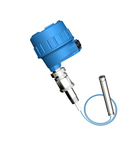
FT8051serial RF admittance Well Detector adopts RF admittance plus three-terminal driven-shield technology. It is comprised of one electronic unit, one connecting coaxial cable and one cable sensing element (or probe), either integral or remote installation could be chosen by clients. This product line is mainly used for deep well detection.
》》》》Operation Principle
As stems from capacitance level control technology, the Radio frequency admittance technology is a more advanced level control technology with a better coating rejection ability (material adhere on the sensing element is called as coating)、more reliable operation、higher accuracy、wider application. “Admittance” in Radio Frequency Admittance means the reciprocal of impedance. Under basic electrical theory, it is comprised of the value of resistance, capacitance & inductance. While “Radio frequency” means high frequency radio wave, so the radio frequency admittance could be understand as a method to measure admittance through high frequency radio wave. High frequency sine-wave oscillator sends a stable detect signal to accurate measure the admittance value of the sensing element (installed on the process vessel) through the capacitance bridge, under direct working mode, the instrument output will increase along with the level arise.
The main differences between the “Radio Frequency ” technology and simple capacitance technology are different measuring variables、three-terminal driven-shield technology and the addition two important circuits, those are progressive improvement base on long time industry experiences. The above techniques not only resolve the connecting cable interference and temperature drifting, but also eliminate the process material coating on the sensing element tip under integral installation condition. The two important circuits are: High accurate oscillator buffer and alternating transition chopper driver.
For a vessel with strong conductive material inside, since the process material is conductive, so the ground could be seen as on the surface of the sensing element insulating layer, for sensing element, it is a pure capacitance. Along with the vessel layout, there will has some coating on the sensing element rod, the coating has impedance, as a result, the previous pure capacitance become a
complex impedance which comprise of capacitance and resistance. This will cause two problems.
The first problem is the impedance of the coating in probe equivalent circuit will pull the oscillator down, change the bridge output, cause measuring error(pure capacitance does not consume energy as process material to be seen as capacitance to probe). We overcome this problem by integrating a special buffer amplifier between the oscillator and bridge to compensate for current flow in the probe circuit. This assures that the oscillator voltage is stable and the signal on the probe is stable.
The second problem for conductive material measurement is the build-up left on the sensing element when the Level goes down. The build-up contains both capacitance and resistance and is connected to ground through the actual level on the probe. The build-up is seen by the measuring circuit as level. If the material is very conductive the whole coating will be read as level Sketches and equivalent circuit and the more conductive the material is, the more error will occur.
But there is no material is totally conductive. From electricity theory, coating could be seen as a resistor, the build-up on the sensing element could be seen as a transmit wire which made up by an infinite number of small resistances and capacitances, and the coating impedance of capacitance & resistance is the same value if the build-up is long according to mathematical theory. So we use the alternating transition chopper driver to measure the capacitance and resistance parts of the coating separately, then the total measured capacitance is Clevel+Ccoating ,minus the same resistance value as Ccoating,we obtain the real level value with virtually no coating error. E.g.
Cmeasure =Clevel + Ccocating
Clevel =C measure - Ccoating
=Cmeasure - R
》》》》Character
Ø Intrinsic safe design: two wire intrinsic safe design both for electronic unit and sensing element
Ø Free Maintenance: No period clean or re-calibration needed as no moving parts exist, the parts will
not occur block、broken or abrasion
Ø Coating rejection:Driven-shield electronic design makes the instrument ignore the coating affection
on the vessel wall or sensing element
Ø No drifting:will not drift along with the process temperature or density change
Ø Reliable Service life:unique technology give the instrument over 15 years service period
Ø Safety Protection:Built-in sensing element input protection avoid the instrument destroyed under
static energy/surge or electronic-chemical condition
》》》》Typical Application
Ø Water level detection of deep well in oil field
Ø Underground water level measurement and environmental protection in urban areas
Ø Detection of water level in power plant
Ø Water level detection of deep well in Waterworks
Ø Measuring rate of facility: CAT I, transient over voltage 1500V, only use the equipment for measurements within measurement category I
Ø Output: 4~20mA
Ø Measuring Type:Level(DIR) or Distance(REV) field adjustable
Ø Power requirement:15~35VDC
Ø Dissipation power: less than 0.5W
Ø Accuracy: 1% FS
Ø Temp. Effect: 0.25% / 10℃(18℉)
Ø Load Resistance: 24VDC output loop resistance 450Ω
Ø Ambient Temp.:T5:-40~+70℃(-40~158℉);T6:-40~+60℃(-40~140℉)
(Effect of the process temperature on the environment temperature should not exceed the
environment temperature requirements of the instrument.)
Ø Response Time: <0.5second
Ø Time Delay: 0.5~80seconds adjustable
Ø Spark protection (for sensing element): anti-surge strike 1KV, anti-static 4KV/8KV
Ø Radio protection(Built-in filter):instrument pass through 10V/m space electromagnetic field and
3V/m electromagnetic field current injection tests
Ø Measuring Depth: Max. 1000m(Range: 0-180m)
Ø Cable length:5m(197″)(standard),0.1(3.9″)~50m(1968.5″)(optional),
>50m(1968.5″)~ 100m(3937″)(consult factory)
Ø Electrical connection:M20×1.5 (3/4” NPT optional )
Ø Process connection:NPT Thread(standard, BSPT optional) , Flanges (optional)
Ø Process Temp.: -20~+120℃(-4~248℉)
Ø Process pressure: ≤1.6MPa(232psi)
Ø Probe Material:304SS/PVDF
Ø Housing Material: Die casting aluminum epoxy coating
Ø Ingress protection:IP67
Ø Explosion-proof rating:Exia IIC T5/T6 Ga
Ø Approval:PCEC/NEPSI, for other approval please consult factory