

 Products
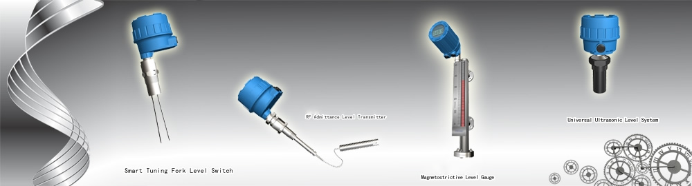
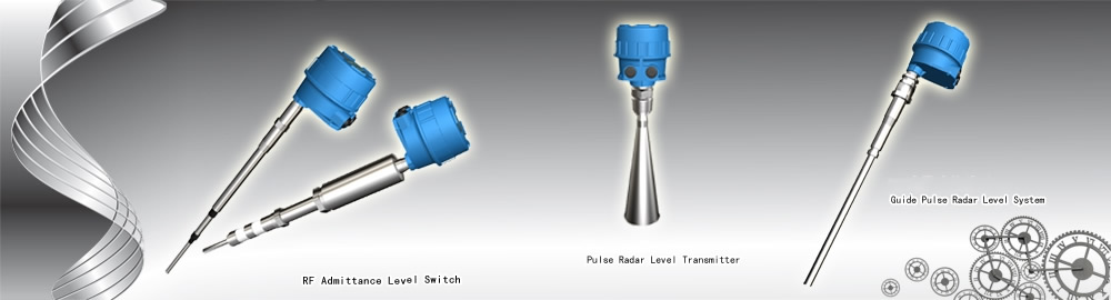
FT8062 series RF Admittance Continuous Level Syste
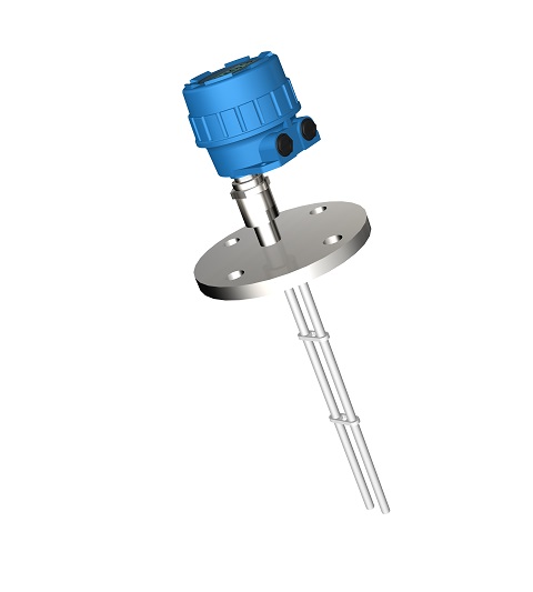
The FT8062 Series general-purpose smart RF admittance level system is used for most continuous level measurements. It is suitable for most industrial or civil applications where measuring level of liquids, powders, slurries and interface is desired. The equipment can be either installed indoor or outdoor, no special mounting requirements needed.
It is comprised of one electronic unit, a set of explosion-proof housing and one rigid or cable sensing element (or probe). These components can be connected in an integral configuration or a remote configuration where all electrical components are mounted away from the measuring point The sensing element can be manufactured of many different metals and insulators depending on the specific application
》》》》Operation Principle
As stems from capacitance level control technology, the Radio frequency admittance technology is a more advanced level control technology with a better coating rejection ability (material adhere on the sensing element is called as coating)、more reliable operation、higher accuracy、wider application. “Admittance” in Radio Frequency Admittance means the reciprocal of impedance. Under basic electrical theory, it is comprised of the value of resistance, capacitance & inductance. While “Radio frequency” means high frequency radio wave, so the radio frequency admittance could be understand as a method to measure admittance through high frequency radio wave. High frequency sine-wave oscillator sends a stable detect signal to accurate measure the admittance value of the sensing element (installed on the process vessel) through the capacitance bridge, under direct working mode, the instrument output will increase along with the level arise.
The main differences between the “Radio Frequency ” technology and simple capacitance technology are different measuring variables、three-terminal driven-shield technology and the addition two important circuits, those are progressive improvement base on long time industry experiences. The above techniques not only resolve the connecting cable interference and temperature drifting, but also eliminate the process material coating on the sensing element tip under integral installation condition. The two important circuits are: High accurate oscillator buffer and alternating transition chopper driver.
For a vessel with strong conductive material inside, since the process material is conductive, so the ground could be seen as on the surface of the sensing element insulating layer, for sensing element, it is a pure capacitance. Along with the vessel layout, there will has some coating on the sensing element rod, the coating has impedance, as a result, the previous pure capacitance become a
complex impedance which comprise of capacitance and resistance. This will cause two problems.
The first problem is the impedance of the coating in probe equivalent circuit will pull the oscillator down, change the bridge output, cause measuring error(pure capacitance does not consume energy as process material to be seen as capacitance to probe). We overcome this problem by integrating a special buffer amplifier between the oscillator and bridge to compensate for current flow in the probe circuit. This assures that the oscillator voltage is stable and the signal on the probe is stable.
The second problem for conductive material measurement is the build-up left on the sensing element when the Level goes down. The build-up contains both capacitance and resistance and is connected to ground through the actual level on the probe. The build-up is seen by the measuring circuit as level. If the material is very conductive the whole coating will be read as level Sketches and equivalent circuit and the more conductive the material is, the more error will occur.
But there is no material is totally conductive. From electricity theory, coating could be seen as a resistor, the build-up on the sensing element could be seen as a transmit wire which made up by an infinite number of small resistances and capacitances, and the coating impedance of capacitance & resistance is the same value if the build-up is long according to mathematical theory. So we use the alternating transition chopper driver to measure the capacitance and resistance parts of the coating separately, then the total measured capacitance is Clevel+Ccoating ,minus the same resistance value as Ccoating,we obtain the real level value with virtually no coating error. E.g.
Cmeasure =Clevel + Ccocating
Clevel =C measure - Ccoating
=Cmeasure - R
Base on different variable measurement, through driven shield technology for the cable and adopt the special buffer and chopper circuits, the three improvements give RF Admittance technology a unique vitality in most industry applications。
FT8062 serial smart RF admittance level product adopts 21th century intelligence technologies which provide a high stability/safety/accuracy measurement for the applications. Except original functions, FT8062 serial also adds software processing and digital communication function which extremely increasing the instrument accuracy、self diagnosis and reliability.
》》》》Character
Ø Intrinsic safe design: two wire intrinsic safe design both for electronic unit and sensing element
Ø Free maintenance: No period maintain or replacement needed as other paddle、vibration or
mechanical switches, the parts will not occur block、broken or abrasion
Ø Coating rejection: Driven-shield electronic design makes the instrument ignore the coating
affection on the vessel wall or sensing element, no period clean or re-calibration needed.
Ø Chemical compatible: Variable sensing element design could meets any process material
requirements.
Ø Wide application: process temperature could run from -183℃~815℃, process pressure
could be vacuum~100bar.
Ø No drifting: will not drift along with the process temperature or density change
Ø Reliable Service life: unique technology give the instrument over 15 years service period
Ø Safety Protection: Built-in sensing element input protection avoid the instrument destroyed
under static energy/surge or electronic-chemical condition.
Ø Easy installation: instrument could be mounted in the field through the vessel screw or flange,
Ø could be selected as integral or remote configuration, easy for installation and calibration
Ø Smart: Software data processing upgrade the accuracy to higher level, built-in self-diagnosis function
Ø Communication: HART Protocol communication
Ø Field calibration button: adjustable calibration button provides easy field calibration
》》》》Typical Application
Ø Liquid:conductive and insulating liquid(include liquefied gas)
Ø Slurry:conductive and insulating slurry
Ø Granular:food、plastic chips、coal etc
Ø Interface:liquid interface between two different dielectric constants
Ø Powder:plastic powder、cement or fly ash etc.
》》》》Specifications
Ø Measuring rate of facility: CAT I, transient over voltage 1500V, only use the equipment for measurements within measurement category I
Ø Output: 4~20mA HART protocol
Ø Measuring Type:Level(DIR) or Distance(REV) software adjustable
Ø Power requirement:12~35VDC Communication requirements: 15~35VDC
Ø Dissipation power: less than 0.5W
Ø Accuracy: 0.5% FS
Ø Linearity: software adjustable 10-point nonlinearity correction (if necessary)
Ø Temp. Effect: 0.2% / 10℃(18℉)
Ø Load Resistance: 24VDC output loop resistance 600Ω
Ø Ambient Temp.:T5:-40~+70℃(-40~158℉);T6:-40~+60℃(-40~140℉)
(Effect of the process temperature on the environment temperature should not exceed the
environment temperature requirements of the instrument.)
Ø Response Time: <1 second
Ø Time Delay: 1~90 seconds (software adjustable)
Ø Spark protection (for sensing element): anti-surge strike 1KV, anti-static 4KV/8KV
Ø Radio protection(Built-in filter):instrument pass through 10V/m space electromagnetic field and
3V/m electromagnetic field current injection tests
Ø Range: 20,000PF (Max.), max. length 1000m(39370”)(different probe has different range)
Ø Cable length:5m(197″)(standard),0.1(3.9″)~50m(1968.5″)(optional),
>50m(1968.5″)~ 100m(3937″)(consult factory)
Ø Electrical connection:double M20×1.5 (3/4” NPT optional )
Ø Process connection:NPT Thread(standard, BSPT optional) , Flanges (optional)
Ø Housing Material: Die casting aluminum epoxy coating
Ø Ingress protection:IP67
Ø Explosion-proof rating:Exia IIC T5/T6 Ga
Ø Approval:PCEC/NEPSI, for other approval please consult factory
》》》》Probe(sensing element) Specifications
|
Probe No. |
Probe Insertion Length(IL) |
DSH |
Wetted Material |
Insulation |
S.E. Mounting |
S.E. Type |
Weight/ anchor |
Temperature/Pressure |
Application |
|
78 |
S.t.500mm(19.7")/250mm(9.8”) Max. 2m(78.7") |
250mm(9.8")/80mm(3.1”) 450mm(18”)/650mm(26”) |
304SS(s.t.) Other optional |
PPS |
3/4"BSPT |
O.D. 9mm(0.35") |
NO |
230℃/1.0MPa (446℉/145psi) 120℃/1.6MPa (248℉/232psi) |
Mid-Temperature Low pressure |
|
82 |
S.t.500mm(19.7") Max.5m(197") Rod |
250mm(9.8") Other optional |
304SS( s.t.) |
Ceramic |
1 1/4"BSPT |
O.D. 9mm(0.35") Three terminal |
NO |
815℃/0.1MPa (1500℉/15psi) 300℃/2.5MPa (572℉/363psi) |
High temperature |
|
82A |
S.t.500mm(19.7") Max. 25m(984") Cable |
250mm(9.8") Other optional |
304SS( s.t.) |
Ceramic |
1 1/4"BSPT |
O.D. 4mm(0.16”) Three terminal |
NO |
815℃/0.1MPa (1500℉/15psi) 300℃/2.5MPa (572℉/363psi) |
High temperature Long range |
|
82B |
S.t.500mm(19.7") Max. 5m(197") Rod |
250mm(9.8") |
304SS( s.t.) |
Ceramic |
1 1/4"BSPT |
O.D. 9mm(0.35") Three terminal |
NO |
815℃/0.1MPa (1500℉/15psi) 300℃/16MPa (572℉/2320psi) |
High-temperature High-pressure |
|
82C |
S.t.500mm(19.7") Max.5m(197") Rod |
250mm(9.8") Other optional |
316L( s.t.) |
Ceramic |
1 1/4"BSPT |
O.D. 9mm(0.35") Three terminal |
NO |
815℃/0.1MPa (1500℉/15psi) 300℃/10MPa (572℉/1450psi) |
High-temperature Corrosion |
|
84 |
Max. 3m(118") |
0mm(0") |
304SS( s.t.) |
PTFE/FEP |
3/4"BSPT |
O.D.12mm(0.47") Two terminal Rod |
NO |
150℃/4.0MPa (302℉/580psi) 40℃/6.3MPa(104℉/913psi) |
Short range Corrosive liquid |
|
85 |
Max.30m(1181") |
0mm(0") |
304SS( s.t.) |
PVDF |
1"BSPT |
O.D. 8mm(0.31") Two terminal Cable |
YES |
120℃/4.0MPa (248℉/580psi) 40℃/6.3MPa(104℉/913psi) |
Long range liquid, powder |
|
85A |
Max. 30m(1181") |
0mm(0") |
304SS( s.t.) |
PVDF |
1"BSPT |
O.D.12mm(0.47") Two terminal Cable |
YES |
120℃/4.0MPa (248℉/580psi) 40℃/6.3MPa(104℉/913psi) |
Long range liquid, powder heavy duty |
|
86 |
Max.22m(866") |
0mm(0") |
304SS( s.t.) |
PTFE |
1"BSPT 1"NPT |
O.D. 4mm(0.16") Two terminal Cable |
YES |
230℃/2.5MPa (446℉/363psi) 40℃/4.0MPa(104℉/580psi) |
Solid/powder Long range |
|
86A |
Max. 22m(866") |
0mm(0") |
304SS( s.t.) |
PTFE |
1"BSPT 1"NPT |
O.D. 8mm(0.31") Two terminal Cable |
YES |
230℃/2.5MPa (446℉/363psi) 40℃/4.0MPa(104℉/580psi) |
Solid/powder Long range heavy duty |
|
87 |
Max. 20m(787") |
80mm(3.1") Other optional |
304SS( s.t.) |
FEP |
3/4"BSPT |
O.D. 2.4mm(0.094") Two terminal Cable |
YES |
150℃/4.0MPa (302℉/580psi) 40℃/6.3MPa(104℉/913psi) |
Interface/liquid Long range |
|
89 |
Max. 1000m(39370") |
0mm(0") Other optional |
304SS( s.t.) |
PVDF |
3/4"BSPT |
O.D. 5mm(0.2") Three terminal Cable |
YES |
120℃/4.0MPa (248℉/580psi) 40℃/6.3MPa(104℉/913psi) |
Long range liquid Interface |
|
90 |
Max. 5m(197") |
0mm(0") |
304SS( s.t.) |
PTFE |
1 1/2"BSPT |
O.D. 38mm(1.5") Center shield ground Two terminal rod |
NO |
230℃/2.5MPa (446℉/363psi) 40℃/6.3MPa(104℉/913psi) |
Insulating liquid |
|
91 |
Max. 4m(157") |
0mm(0") |
304SS( s.t.) |
FEP |
DN80PN16 |
Twin probe total covered Two terminal rod |
NO |
150℃/4.0MPa (302℉/580psi) 40℃/6.3MPa (104℉/913psi) |
Short range Corrosive liquid |
|
92 |
Std. 500mm(19.7") Max. 2m(78.7") |
250mm(9.8") Other optional |
304SS(s.t.) Monel optional |
PTFE |
3/4"BSPT |
O.D.9mm(0.35") Three terminal Rod |
NO |
230℃/4.0MPa (446℉/580 psi) 40℃/6.3MPa (104℉/913psi) |
Insulating liquid |
|
93 |
Max. 3m(118") |
0mm(0") |
304SS( s.t.) |
PTFE |
1 1/2"Tri-clamp Other optional |
O.D. 12mm(0.47") Two terminal Rod |
NO |
230℃/2.5MPa (446℉/363psi) 40℃/6.3MPa(104℉/913psi) |
Sanitary 3A probe |
|
95 |
Max. 5m(197") |
0mm(0") Other optional |
304SS( s.t.) |
PTFE |
1"BSPT 1"NPT |
O.D.18mm(0.71") Two terminal Rod |
NO |
230℃/4.0MPa (446℉/580psi) 40℃/6.3MPa (104℉/913psi) |
Mid temp./press. Interface, desalter |
NOTE: 1. For agitation conditions, recommend to use bracket (rigid probe) or anchor (cable probe) for support. 2. DSH (shield length) must go into the vessel wall at least over 50mm. 3. For solid applications, the maximum length to go into cone should not bigger than 20% of the vessel O.D. 4. The maximum active range of FS89 is 400m. 5. For FS84 PTFE material, temp./pressure could reach 230℃/2.5MPa。6. For following applications, cooling extension is needed: 1) FS95 under or above 180℃/4.0MPa applications; 2) FS82 under or above 400℃ applications.