

 Products
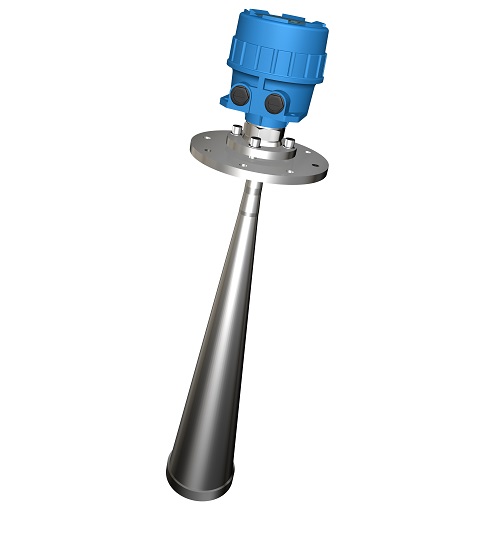
FT816X Series Radar Level System
》》》》Operation Principle
Radar is a technology which is first adopted in military area. Send electromagnetic wave and receive its
reflection to measure the distance and direction of the target.
Extremely short microwave impulses are emitted by the antenna system to the measured product, reflected by the product surface and received again by the antenna system. The time from emission to reception of the signals is proportional to the level in the vessel but it is hardly to verify (nanosecond range) because of the spread speed of the electromagnetic wave. However, FT8161 serial radar level system adopts a special time spreading procedure to enable the reliable and precise measurement of the extremely short signal running times, then gives a accurate calculation of the distance between the antenna and process material surface. The radar sensors are available in different frequency ranges, this ensures the optimum solution for the different applications. The proven signal processing analysis the reflections in the vessel based on long-standing experience and detects the level signal reliably. The adaptation to the respective application is really simple through the selection of the application parameters.
》》》》Characters
As adopts 26GHZ emit frequency, so FT816X has following advantages:
Ø More suitable for small granular measure under shorter wave
Ø Small beam angle give more anti-interference ability to increase accuracy and reliability
Ø Exquisite antenna give more chances for easy installation and quick antenna protection adding such as dust cover
Ø Shorter dead zone could works better in small vessels
Ø Advanced micro-processer and unique Echo Discovery technology could resolve most difficult field applications
Ø Under a lower transmit power, the microwave impulses radar system could be installed in any metal non-metallic vessels and no harmful to personnel or environment
》》》》Typical Application
Ø Liquid、light slurry、granular、interface、powder
Ø water、acid、dilute alkali、oil、food、raw coal、coal powder、cement、lime、flour
Ø Measuring rate of facility: CAT I, transient over voltage 1500V, only use the equipment for measurements within measurement category I
Ø Output: 4~20mA HART protocol
Ø Measuring Type:Level(DIR) or Distance(REV) software adjustable
Ø Microwave Frequency: 26G
Ø Power Supply:15~35VDC(Standard) 21.6~26.4VDC(intrinsic safe)
Ø Dissipation Power: less than 0.5W
Ø Accuracy: 01.%FS or 5mm(which greater)
Ø Resolution: 1mm
Ø Temp. Effect: 2.5mm/10℃(18℉)
Ø Load Resistance: 24VDC output loop resistance 450Ω
Ø Ambient Temp.:T5:-40~+70℃(-40~158℉);T6:-40~+60℃(-40~140℉)
(Effect of the process temperature on the environment temperature should not exceed the
environment temperature requirements of the instrument.)
Ø Response time: <2 second
Ø Time Delay:0~40秒 (software adjustable)
Ø Range:FT8161: 0~30m(liquid); FT8162: 0~30m(solid); FT8163: 0~70m(liquid/solid)
Ø Dead zone: Antenna edge(30m range); 800mm away from antenna edge(70m range)
Ø Electrical connection:double M20×1.5 (3/4” NPT optional )
Ø Process connection:1 1/2” NPT Thread(standard, BSPT optional) , Flanges (optional)
Ø Housing Material: Die casting aluminum epoxy coating
Ø Ingress protection:IP67
Ø Explosion-proof rating:Exia IIC T5/T6 Ga
Ø Approval:PCEC/NEPSI, for other approval please consult factory
》》》》FT816X Installation Requirements
l Installation、Utility & Maintenance of the instrument should comply with the instruction manual and
GB50257《Construction & Verification Standard of Electrical apparatus mounting in explosion or flaming dangerous area》、GB3836.15 & GB3836.13 requirements.
l The mounting location of the instrument should free of vibration, high temperature, corrosive atmospheres,
or any possibility of mechanical damage for maximum service life. If this is not possible, consider a remote system installation. Ambient temperature should be between -40 ~70oC (-40 ~158oF ).
l Instruments installed outdoors in areas of lightning strikes should be installed with lightning protection.
l DO NOT ADOPT MONO-COMPOSITION ENCAPSULAION SEALING inside of instrument housing since most of that kind of encapsulation will contain acetic acid. (Acetic acid could decay the electrical component.) Please consider to use SPECIAL DOUBLE-COMPOSITION ENCAPSULATION (non-erosive).
l The instrument has ground terminal on its housing. Please connect the terminals to the field ground properly during installation. For non-metallic vessel/tank installation, the filed should provide a standard ground. CONNECT TO DYNAMIC GROUND IS FORBIDDEN!
l Cable inlet should meet GB4208 standard requirements reach IP65 code to ensure reliable electrical connections. It will avoid water or other corrosive gas destroys the electronic unit.
l Do not open sensing element or loosen sealed gland. That may cause system leakage.
l Do not install the sensing element directly under a flow stream or feed line. If this is the only position available, use a baffle or shield above the probe to keep it out of the flow stream. Keep the feed line away from the path of the microwave signals.
l Only the mounting screw or flange part of the sensing element need be well connected to the vessel, reliable sealed and electrical connected properly. Any other parts of the sensing element should not touch the vessel for good insulation.
l Each antenna has certain beam angle during emission, so avoid any obstacle go into the wave radiation area between the antenna edge to the process material surface. Vessel installations, such as e.g. ladders, limit switches, heating spirals, struts, etc., can cause false echoes and impair the useful echo. If necessary, recommend to run " false echo storage”.
l Ensure the highest level could not go into the measuring dead zone.
l Remain certain distance between the instrument and the vessel wall and keep the instrument emission direction be vertical to the process material surface as much as it could.
l For explosion-proof instrument installation, cable inlet should come with approved cable accessory such as XP fittings or XP steel conduit sealing according to GB3836.1 & GB3836.2 explosion-proof standard requirements.
l For intrinsic-safe instrument installation, the loop should come with approved barrier according
to GB3836.1 & GB3836.2 explosion-proof standard requirements.
l 24VDC Instrument power noise should be lower than 100mV.
l Power wire should meet IEC60245/60227 standard requirements Recommended as 3 terminal armature
cable, cable O.D. should less than 12mm, conductor material of the cable is copper, section area should between 0.13 –2.1 mm2(AWG14-26), insulating capability 1500V. And associated switch should meet IEC60947 requirements. Do not make the unshielded cable parallel with power supply cable for long distance..
l Strict follow “STOP OEPN THE LID WHILE POWER ON” during field operation or maintain, recommend
to operate 10 minutes after power off.