

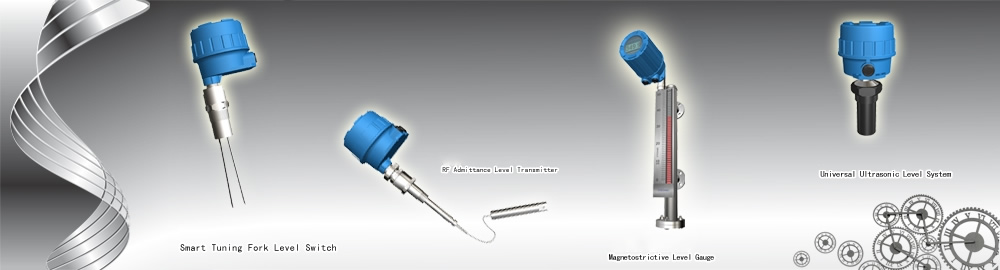
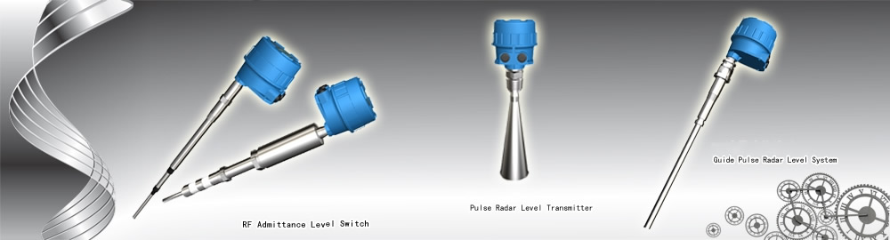
 Products
FT8511 series Magnetostrictive Level System
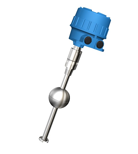
FT8511 serial magnetostrictive level system is made by magnetostrictive principle and advanced material/processing method, it is a two wire Intrinsic Safe level product, could be used for petroleum、petrochemical、chemical、food etc applications,provide precise and reliable process/storage level measurement and control.
》》》》Operation Principle
Sensor is the center of the magnetostrictive monitoring system, and the core sensitive component(magnetostrictive wire) of the sensor need has high adapted ability、strong convert capability of electrical(magnetic) /mechanical wave to transfer the small magnetic vector change to be a mechanical wave. Sensor is comprised of stainless steel rod(inside include supper magnetostrictive wire) and float(inside include rare earth permanent magnet) two parts. While the pulser of electronic part emits a electric pulse transmit along with the magnetostrive wire inside of the steel pipe, the electrical pulse also accompany generate an annular magnetic field vertically to the wire,and the field transmit along with the wire at velocity of light.
When the annular filed of the electrical pulse meets the fix filed of the float, the two magnetic fields interacts each other, then occurs instant torsional force and form a mechanical torsional pulse wave on the wire. This mechanical torsional wave use a fixed speed return to electronic part and be picked up by that part. According to the time difference between the emitted electric pulse and the returned torsional wave, the material level or interface could be accurate calculated out.
》》》》Character
Ø Modular design:The sensing element and electronic unit could be interchange between different system, easy for spare and maintenance.
Ø Remote installation:Suitable for multiple applications, convenience for control and monitoring.
Ø Could be adapted together with float chamber system:Wider applications
Ø HART communication : Built-in two wire field 4-20mA HART protocol
Ø Field keyboard calibration:The two keyboards on the top the electronic could calibrate the high/lower level points easily in the field.
Ø Oil storage tank
Ø Oilcan in gas station
Ø Process tank leakage detection
Ø Variable chemical reagents
Ø Water & wastewater
Ø Other high speed level detection
》》》》Specifications
Ø Measuring rate of facility: CAT I, transient over voltage 1500V, only use the equipment for
measurements within measurement category I
Ø Output:4~20mA,HART digital protocol, output direction software adjustable
Ø Measuring Type:Level(DIR) or Distance(REV) field adjustable
Ø Power requirement:12~35VDC; For communication: 15~35VDC
Ø Dissipation power: less than 0.5W
Ø Accuracy: ≤0.1%FS or 1mm (which greater)
Ø Resolution: ≤0.04%FS or 0.4mm (which greater)
Ø Repeatability: ≤0.04%FS or 0.4mm (which greater)
Ø Linearity correction: 10 points non-linearity correction by software (if necessary)
Ø Temperature Affection: 0.1%/10℃(18℉)
Ø Load resistance:24VDC output loop resistance 600Ω
Ø Ambient Temp.:T5:-40~+70℃(-40~158℉);T6:-40~+60℃(-40~140℉)
(Effect of the process temperature on the environment temperature should not exceed the
environment temperature requirements of the instrument.)
Ø Response Time: < 2 seconds
Ø Time Delay: 1~90seconds adjustable(software)
Ø Range:0~6m(rigid) ,0~20m(flexible cable)
Ø Dead Zone:Upper zone: ≤ 1/2 float height
Lower zone: Rigid sensor- 1 float height;Cable sensor- 250mm to 450mm
Ø Max. process temperature: -40~400℃(for details please see probe specifications)
Ø Max. process pressure: 10 MPa (for details please see probe specifications)
Ø Cable length: max . remote cable 3m
Ø Electrical connection:double M20×1.5 (3/4” NPT optional )
Ø Process connection:NPT Thread(standard, BSPT optional) , Flanges (optional)
Ø Housing Material: Die casting aluminum epoxy coating
Ø Explosion-proof rating:Exia IIB T5/T6 Ga & Exd IIBT5/T6 Gb
Ø Ingress protection:IP67
Ø Approval:CMC, PCEC/NEPSI, for other approval please consult factory
》》》》FT8511 Installation Requirements
l Installation、Utility & Maintenance of the instrument should comply with the instruction manual and
GB50257《Construction & Verification Standard of Electrical apparatus mounting in explosion or flaming dangerous area》、GB3836.15 & GB3836.13 requirements.
l The mounting location of the instrument should free of vibration, high temperature, corrosive atmospheres, or any possibility of mechanical damage for maximum service life. If this is not possible, consider a remote system installation. Ambient temperature should be between -40 ~70oC (-40 ~158oF ).
l Instruments installed outdoors in areas of lightning strikes should be installed with lightning protection.
l DO NOT ADOPT MONO-COMPOSITION ENCAPSULAION SEALING inside of instrument housing since most of that kind of encapsulation will contain acetic acid. (Acetic acid could decay the electrical component.) Please consider to use SPECIAL DOUBLE-COMPOSITION ENCAPSULATION (non-erosive).
l The instrument has ground terminal on its housing. Please connect the terminals to the field ground properly during installation. For non-metallic vessel/tank installation, the filed should provide a standard ground. CONNECT TO DYNAMIC GROUND IS FORBIDDEN!
l Cable inlet should meet GB4208 standard requirements reach IP65 code to ensure reliable electrical connections. It will avoid water or other corrosive gas destroys the electronic unit.
l Do not open sensing element or loosen sealed gland. That may cause system leakage.
l Do not install the sensing element directly under a flow stream or feed line. If this is the only position available, use a baffle or shield above the probe to keep it out of the flow stream.
l Only the mounting screw or flange part of the sensing element need be well connected to the vessel, reliable sealed and electrical connected properly. Any other parts of the sensing element should not touch the vessel to ensure float works well.
l Keep any ferromagnetic material at least 200mm away from the sensing element.
l Consider temperature insulation bracket if the FS48 sensing element be used in 120℃ above.
l Keep the rigid sensing element at least 200mm away from the vessel wall. For cable probe, keep it as straight as possible and at least 300mm away from the vessel wall to avoid the float hitting the vessel wall.
l For agitation、gas/material flow fluctuation vessel, except avoid directly mechanical damage on sensing element, middle support (for rigid probe)/bottom anchor (for cable probe) of sensing element need be considered to avoid indirect mechanical broken under long-term utility. Please note: the support/anchor must be insulated with the sensing element. The insulating material should be high insulation, low hardness, lubricant and anti-abrasion material such as PTFE etc.
l For explosion-proof instrument installation, cable inlet should come with approved cable accessory such as XP fittings or XP steel conduit sealings according to GB3836.1 & GB3836.2 explosion-proof standard requirements.
l For intrinsic-safe instrument installation, the loop should come with approved barrier according to GB3836.1 & GB3836.2 explosion-proof standard requirements.
l 24VDC Instrument power noise should be lower than 100mV.
l Power wire should meet IEC60245/60227 standard requirements Recommended as 3 terminal armature cable, cable O.D. should less than 12mm, conductor material of the cable is copper, section area should between 0.13 –2.1 mm2(AWG14-26), insulating capability 1500V. And associated switch should meet IEC60947 requirements. Do not make the unshielded cable parallel with power supply cable for long distance..
l Strict follow “STOP OEPN THE LED WHILE POWER ON” during field operation or maintain, recommended operate 10 minutes after power off.